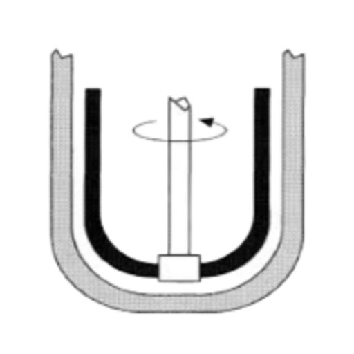

We manufacture these agitators with excellent tested material ensuring reliability and durability. These Industrial agitators are used in several small as well as large scale industries.

However, if the agitator is "homemade", we need a lot more data, as other posters have requested, to help assess the situation.Helix Offers Wide range of Industrial Agitator that are having various application is process industry. If your application was specified correctly and you purchased an agitator from a reputiable company (Chemineer, Lightnin, etc.), I would recommend getting them involved. Given the shaft length and impeller blades position and properties, the shaft diameter is calculated to give a comfortable safety factor of running less than the first critical speed. The agitator shaft length is determined by considering your process requirements (#1) and to maintain good reliability of the agitator (#2) there is no one magic formula.
ANCHOR AGITATOR DESIGN HOW TO
My question is on which basis agitator shaft length to be decided to avoide the damage or how to calculate agitator shaft length I am asking this because on low level alarm (20 %) of tank, agitator is not getting immersed in liquid resulting in frequent damage to bearing due to vibration so we have changed alarm value to 50% instead of 20%. Please share your views.Īgitator shaft length should be calculated on which basis. (Otherwise i have to change my design which i have just freezed for my on going project. I hope this is inline to what is normally practiced. Sometimes in case of elipticle bottom the bottommost impeller dia is kept smaller compare to upper impeller dia. The graphs are easily available for various types of agitator as Nre vs Np. and type of agitator (pitch blade, flat blade etc.). The minimum distance between two impeller has to be same as impeller diameter. If this ratio is greater than 1.2 then go for two impellers else take one.Īs far as distance is concern, the distance between tank bottom to bottommost impeller centre line has to be 1/3 times of tank inside diameter. of impeller is decided by finding the ratio of (height of liquid level * sp. Let me put forward my views and plz correct me if wrong. Length of Agitator Shaft = distance between bearing & agitator (lower impeller)

Thus, Impeller Clearance is Z/3 or T/3 based on the above table. Viscosity, cP (Pa.s):: Max Level, Z/T:: Number of Impellers:: Impeller Clearance (Lower : Upper) This method takes into consideration liquid level (Z), tank diameter (T), number of impellers and fluid viscosity. (Ref.: EEUA, page 5).Īnother method to determine lower impeller clearance is given in "Handbook of Chemical Engineering Calculations" By - Nicholas P. Per unit volume increases as the filling ratio departs from unity. Liquid, however, a filling ratio of 2 is recommended in order to maintain a sufficiently long period of contact between the gas & the liquid. The filling ratio is the ratio of Liquid Depth to Tank Diameter, which is normally between 0.5 - 1.5. Ratio of bottom clearance to vessel diameter should be between 0.1 - 0.4 for a filling ratio of 1.0īut for an Anchor Impeller, clearance is determined by mechanical considerations a clearance of 1in. Referring to procedures laid down in Engineering Equipment Users Association (EEAU) handbook, EEUA HAND BOOK NO.9,Ĭlearance between Impeller & the bottom of the tank:


 0 kommentar(er)
